The term is underway, and so is our build! The frame gets built (on our kitchen counter) and the computer vision program is coming together.
General Updates
The team is back together in Waterloo, and we received the winter term timeline from our supervisors:
- Supervisor Meeting #1 - Jan 16-20
- Website with build log launch - Jan 27
- Digital Brochure information - Feb 3
- Supervisor Meeting #2 - Feb 13-17
- Supervisor Meeting #3 - Mar 6-10
- Mechatronics Capstone Symposium - Mar 24
Most importantly, the project should be demonstratable by March 6th, and symposium ready before March 24th!
On a logistics note, we learned that a package (containg angular contact bearings for the milling system) was lost in transit, and so we’ve ordered another set from China. The new parts are expected to arrive by the end of the month, and so they shouldn’t interrupt our schedule.
Mechanical Updates
Over the last week:
- The frame has been assembled
- The wire feeder has begun
Frame
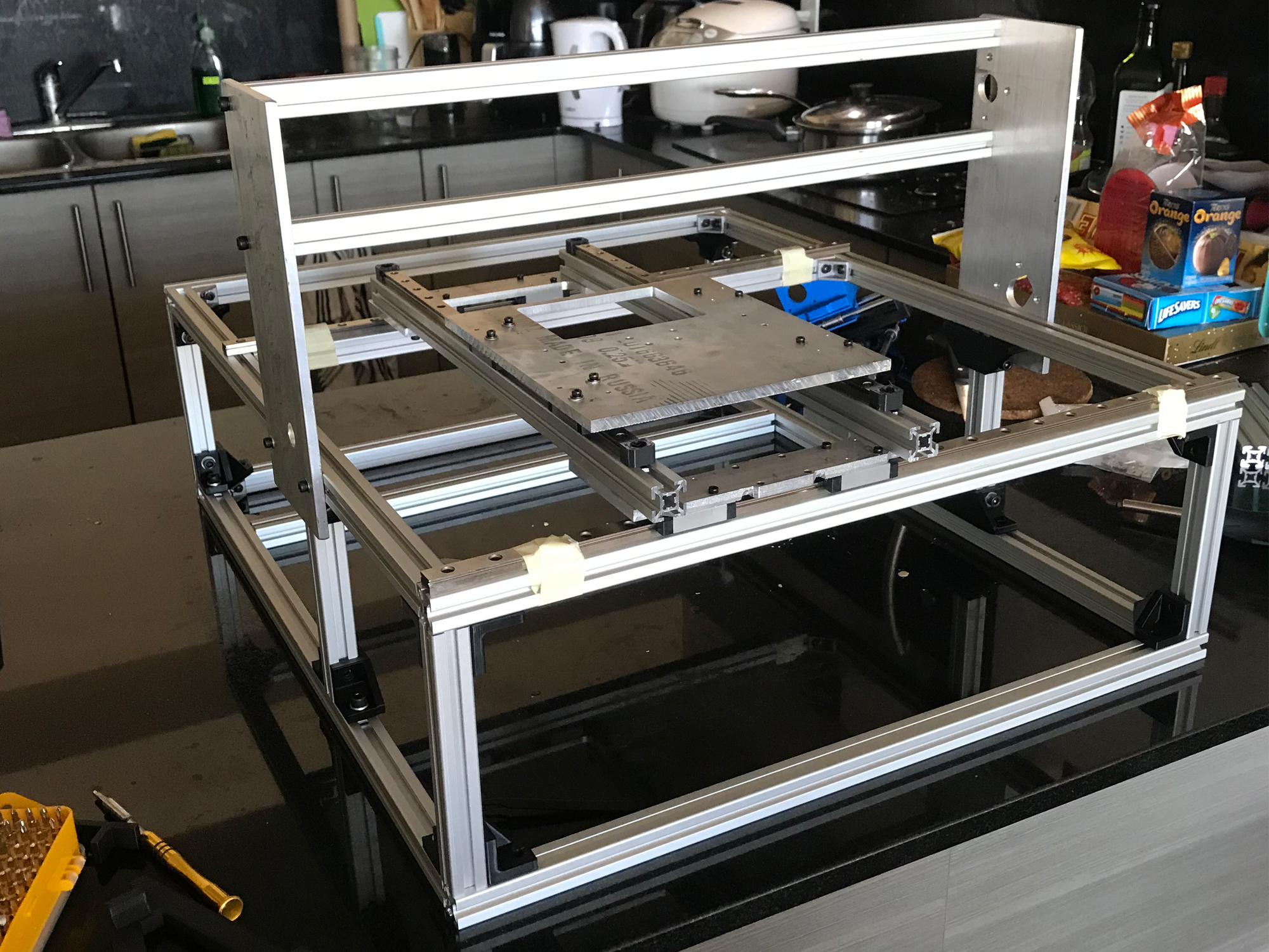
The frame is built primarily using aluminum extrusions, which we sourced from the university’s Engineering Machine Shop (EMS). We were able to purchase the aluminum cut to size, and so all we had to do was put the pieces together. To do this, we used a combination of purchased aluminum brackets and custom 3D-printed brackets.

The full frame, seen on our kitchen counter.
Additionally, the frame uses two machined aluminum plates, which were previously machined over the winter holidays.
Wire Feeding Assembly
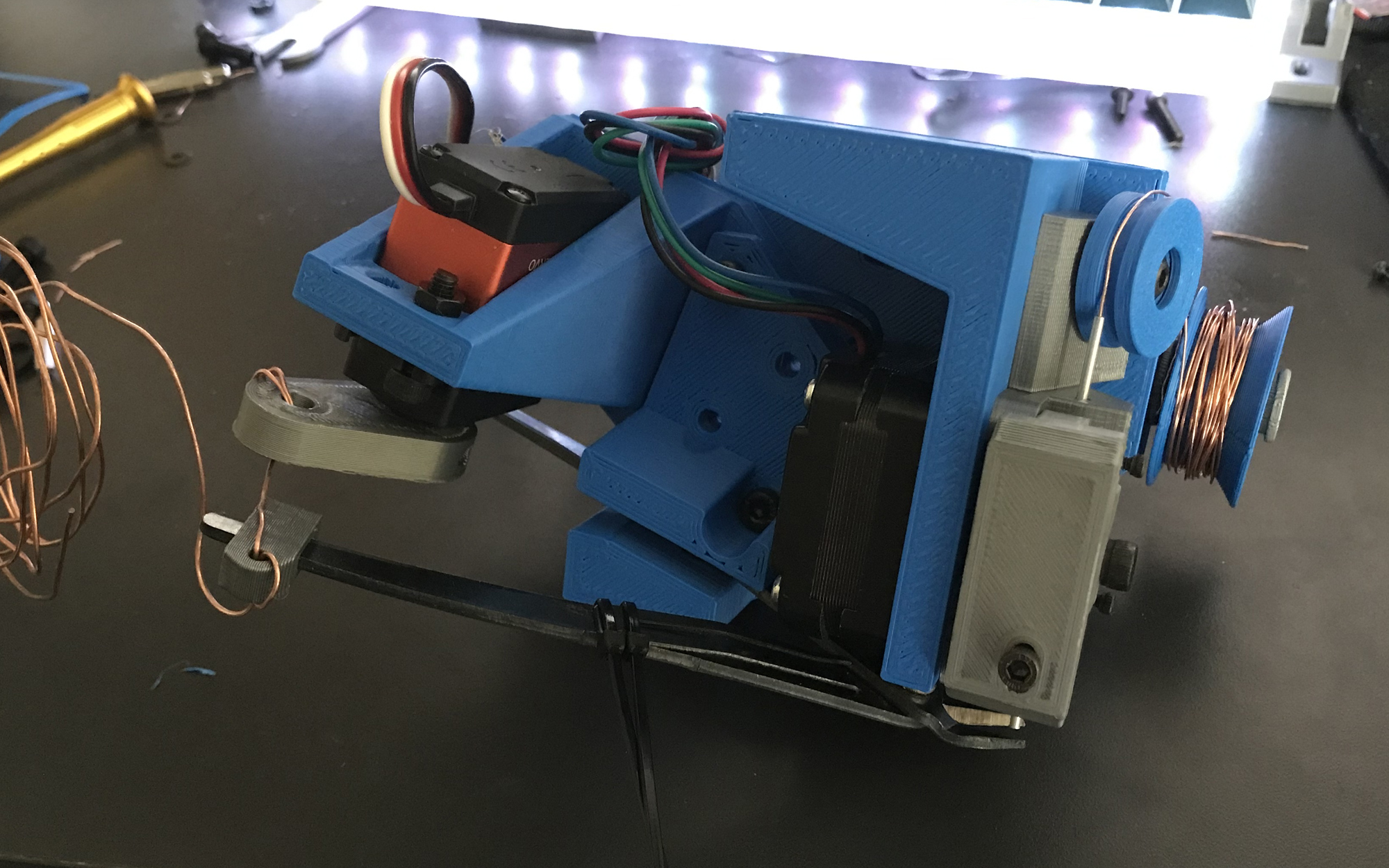
The wire feeding system is modeled after a 3D printer’s extruder, and uses many of the same components. To save costs, and support an iterative rapid prototyping process, the assembly is mostly 3D-printed. This week the parts were printed and assembled, and the wire feeding system is now ready for offline testing and installation.

The wire feeding assembly, before installation to the frame.
Mechanical Next Steps
With the frame assembled, components can now be mounted once they’ve been tested offline. Up first is the wire feeding assembly: we’ll test that it can feed and cut wire on its own, and then mount it to the device.
After that, the via press is our next priority; the metal components have already been machined and cut as necessary, and all that’s left is to 3D print the remaining components and assemble.
Software/Firmware Updates
Over the last week:
- The core of the computer vision program was developed
- Hole detection has been completed
Computer Vision Core
The computer vision program has three main components. First, the general pipeline which involves filtering and post processing the video. The second is an efficient way to tune the parameters. The final component is extracting relevant information such as the position of the holes and the wire. The general pipeline that was developed has the following steps:
Start a camera and store the incoming frames.
Blur the frames to remove some of the noise.
Mask out everything in the frame that is not the wire and the hole.
Use an edge detection algorithm to extract the general shape and position of the wire and the hole.
Combine the detected hole and wire images.
Use the combined image to determine the relative distance between the wire and the hole.
Generate the motor commands to move the hole under the wire.
The process of tuning the parameters efficiently was done by creating a GUI with sliders. These sliders allow us to tune the HSV values that are used to create the mask in step 3. Also, the parameters of the edge detection algorithm can be tuned with these controls.
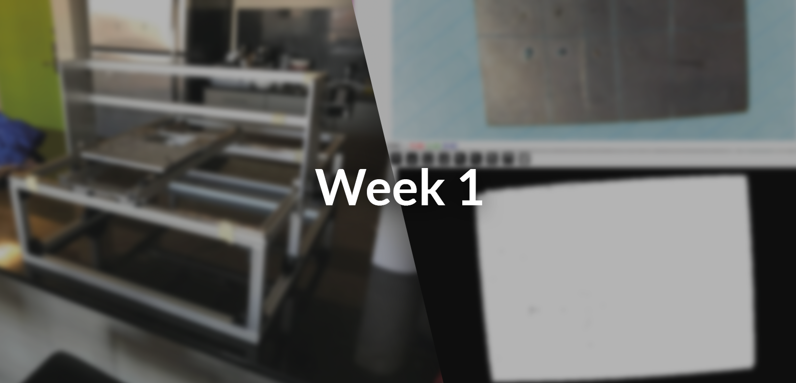
This week, the first 3 steps were fully added into the software. On top of this, the edge detection for the holes was also added and tested. In the image below the processed masked image showing just the hole is on the right and in the left a red circle around that hole on the original video can be seen.

The real video with a circle drawn on the hole and a masked image showing just the hole.
Software Next Steps
Now we need to add the wire detection and combine that with the hole detection process that was created this week. Once this is achieved the wire feeding computer vision will almost be complete. The remaining task will be to extract the position differences between the wire and the hole and determine the correct motor commands to align them.
Another aspect of the software that has yet to be developed is detecting the whole PCB after one side has been milled. This will be used to check the misalignment when the PCB is flipped, before the milling has started on the other side.
