The build continues: more mechanical systems get built and tested, and the electrical team gets moving.
General Updates
This week we had our first supervisor meeting, where we discussed our plans and schedule for the term. An important note from this meeting is that they’d like to see individual components working at our next meeting (which is on the timeline from last week).
Mechanical Updates
Last week, we saw the frame get put together and the wire feeder get started. This week, the following progress has been made:
- The wire feeder has been tested offline and is ready for installation
- The press head assembly process has started, and it’s almost ready for installation
Wire Feeder
The wire feeder has been fully assembled; the wire cutters are installed and connected to the servo, the feeding mechanism is connected to a stepper motor, and commercially-available 0.5 mm wire has been spooled into our specially-sized spool.
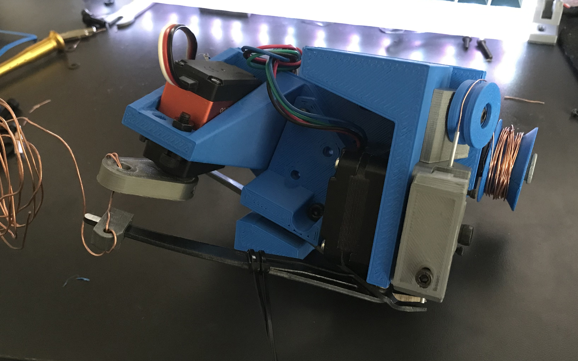
The wire feeding assembly, as seen last week (before testing).
Before installing the wire feeder, we tested it offline to ensure proper operation. The wire feeding worked perfectly, with the wire coming out smoothly and in a relatively straight line. To ensure that the spooled (and therefore coiled) wire came out smooth, we designed the wire path to have a large idler wheel that forces the wire to bend in the opposite direction from its coiling, to help undo the inital curvature.
The wire cutter also works, but this took some iteration before it started working smoothly. First, we had to tune both the servo motor’s arm length and where cutter-motor connection point, to ensure we have the arm length and lever ratio. While our servo motor has a high max torque rating, we’re running it at 5 V (rather than its max operating voltage of 6.8 V), and so we’d prefer to use mechanical advantage as much as possible.
We also had to carefully position the wire cutter, as we’re using old wire cutters (to save costs) with some dull spots. To position the wire close to a sharp area, we had to redesign the 3D-printed cutter mounting piece to fit. We also ran into an issue where our cutter clamping system (which uses screws to press against the cutter) was deforming the 3D-printed piece, and so we redesigned it to be stronger.
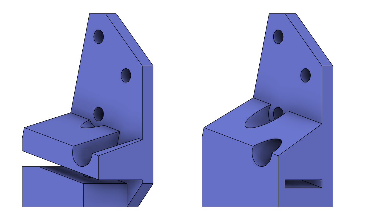
The older wire cutter mount (left), which was prone to deformation, and the new mount (right) which has more material and a closed-loop structure.
Additionally, the computer vision camera (for locating via holes) was installed to the assembly.
Via Press
The wire press parts have been 3D printed. These parts were mostly related to linear motion (bearing holders, shaft holders, etc.), and so they required multiple iterations to get alignments perfect.
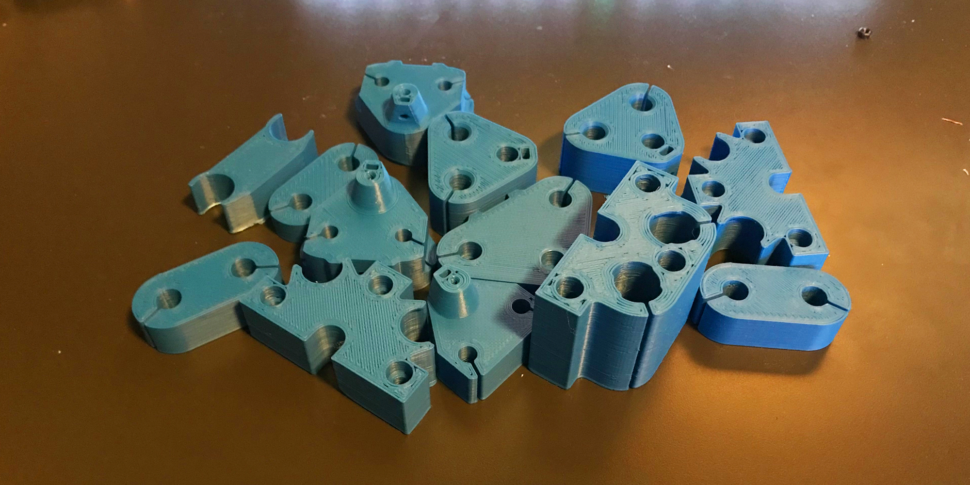
3D printing allows for very rapid iteration.
With the parts printed, the press was first assembled off of the machine to verify alignment of the two pressing arms. Unfortunately, we ran into a slight misalignment:
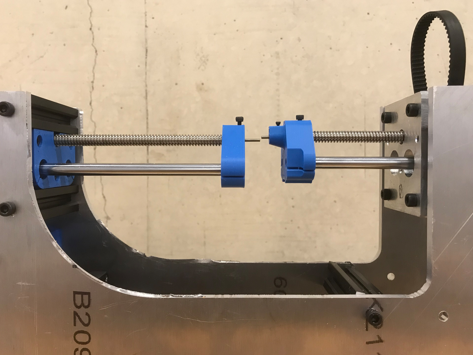
The via press assembly, with the upper and lower arms misaligned.
Fortunately, this can be remedied by filing/grinding the lower press arm’s mounting holes into slots, to allow for some adjustment.
Next Steps
This weekend we’re hoping to fix to the via press alignment issue, and then we can mount both the wire feeder and the press. We decided to mount both at the same time as the need to be aligned with each other to properly feed and press via wires.
Once those components are mounted, we can test their integration as the software/firmware becomes ready. In the meantime, we can get started on the other motion systems, including x- and y-motion, and the PCB flipper (which allows the device to work with both sides of the PCB.)
Software/Firmware Updates
Over the last week:
- General PCB detection was worked on
PCB Detection
For most of the overall process the PCB will be in the same position in the clamp. However, this changes in the middle of the milling process. Once the top side of the PCB is milled the PCB is flipped over so that the bottom can be milled. Due to imperfections in the edge of the PCB and tolerances in the clamp this could cause alignment issues. This creates issues since the flipped version of the PCB will be slightly off from the non-flipped side. So, hole positions will shift slightly after flipping. To remedy this computer vision will be used with a wide-angle camera to capture the whole PCB. Fiducial markers on each corner of the PCB will be drilled and used to compare to the flipped PCB image. By comparing these images, the distances that the holes were shifted can be determined and used to correct the movements in the second half of the milling process.
Below is an image showing the whole PCB masked out and ignoring any traces, holes or scratches on the surface. This is the foundation for the complete system described above.

The real image and a masked image showing just the PCB.
Software Next Steps
Currently we are unable to create fiducial markers as the drilling heads are not fully finished. So, the next few weeks will focus on the wire feeding system. Specifically, the wire detection and hole alignments sections will be worked on.
