We run into a minor purchasing hurdle, the first components get mounted to the frame, and the device moves off of our kitchen counter.
General Updates
Two weeks ago, we had to reorder some bearings that were lost in transit. This week, we received the bearings - but the seller sent the wrong size. Unfortunately, we sourced these bearings from China, which means we can’t get replacements from them soon (due to Lunar New Year). Fortunately, there are alternatives (different designs, different suppliers, etc.), and we’ll decide on our next steps in the coming days.
Mechanical Updates
Last week, the wire feeder finished testing and the via press assembly process began. What did we get up to this week?
- The via press alignment was fixed
- The via press and wire feeder were installed to the frame
- The PCB flipper was assembled and installed
Via Press
As discussed last week, the two pressing arms were misaligned, which would prevent the device from properly forming vias. Grinding the lower arm’s mounting holes worked perfectly, and the press arms are now aligned when they meet at the PCB.
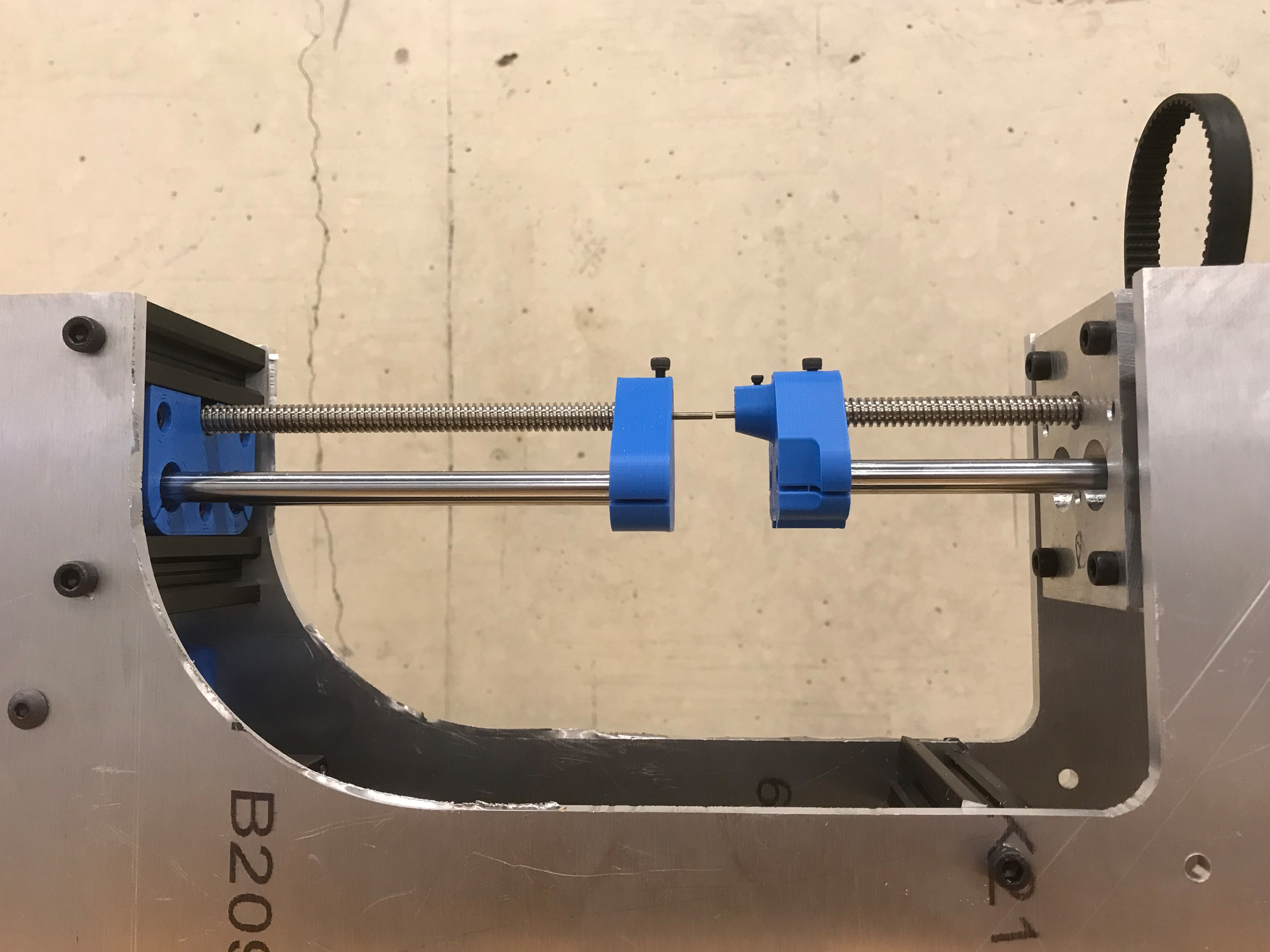
The via press assembly, with the upper and lower arms properly aligned.
With alignment verified, the via press can now be installed to the frame. Unfortunately, we can’t test the pressing performance beforehand, as one of the motors is mounted on the frame due to space constraints.
Via Press and Wire Feeder - Installation
The via press and wire feeder were installed to the frame, using a combination of 3D-printed brackets and purchased metal brackets (much like the frame itself). A great feature of aluminum extrusion with channels is that parts can be mounted anywhere on the extrusion, allowing for fine-tuning of the components’ relative locations.
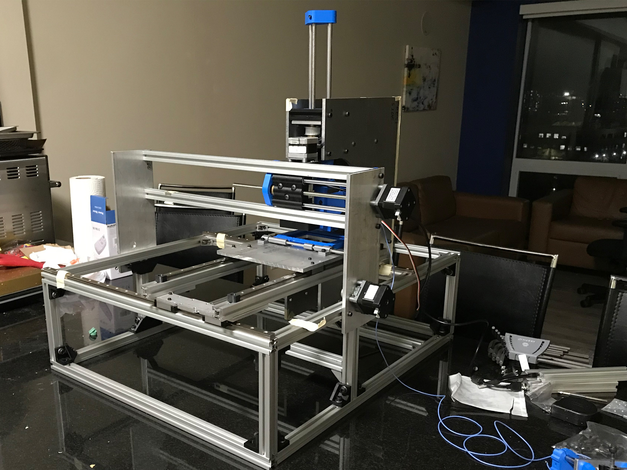
The via press and wire feeder (hard to see due to the angle) installed to the device.
While installing the press, we realized that the design works, but could be optimized for an easier install. If we need to remove the press in the future, we’ll implement some changes to make maintenance and modification easier.
PCB Flipper
To allow the device to interact with both sides of a PCB autonomously, the device needs to rotate the PCB. Our system treats the PCB as a “book page,” where the spine of the “book” is on the surface of the PCB x-y carriage. This allows the PCB to rest flat against the carriage in either operating orientation, which will help rigidity. The flipper is connected to a motor through a belt, and the motor is mounted to the PCB x-y carriage using a 3D-printed bracket. This bracket was designed to be as rigid as possible, with thick walls and lots of gussets, and the stepper mounting holes are slots to allow for adjustable belt tension.
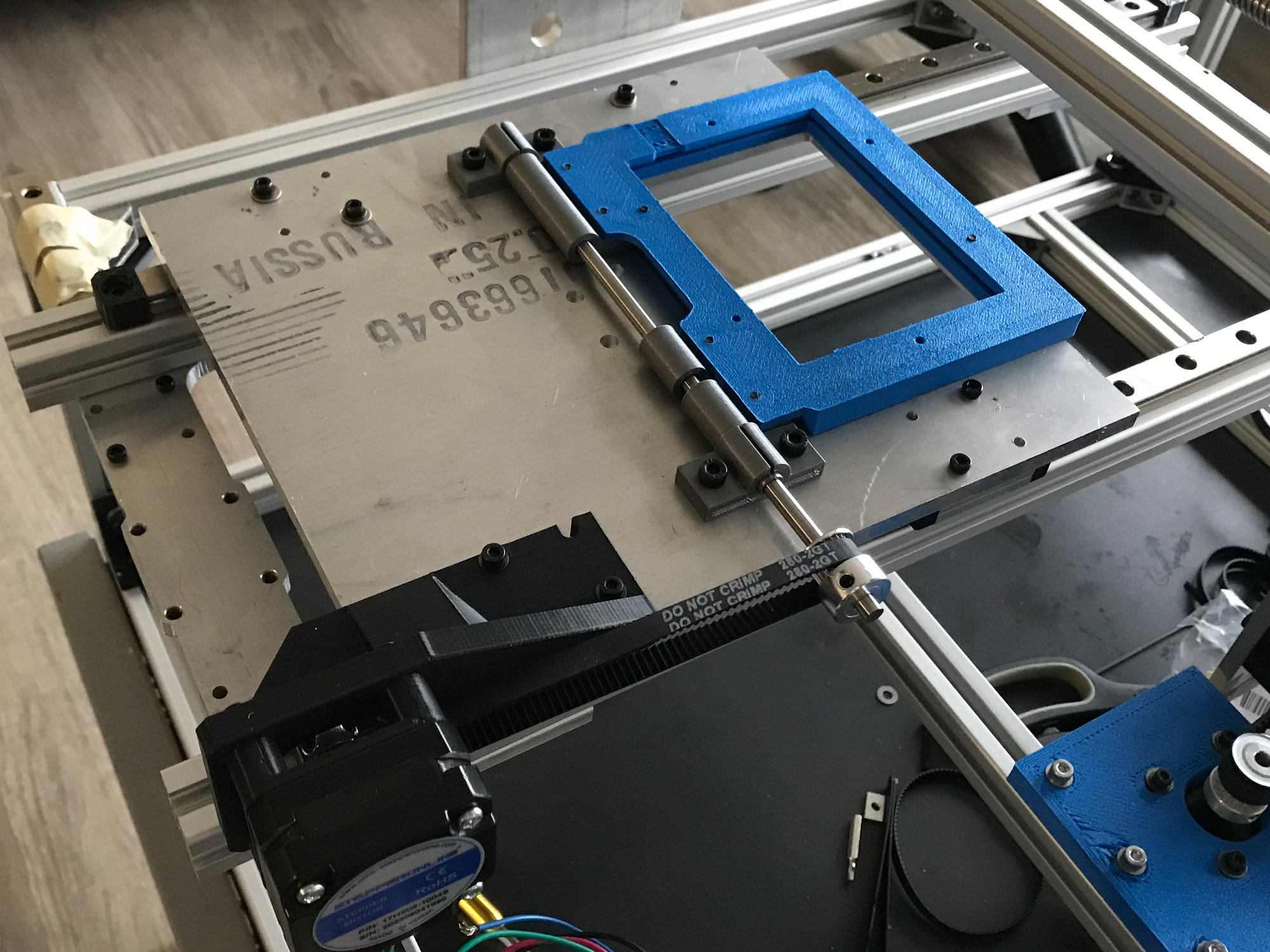
The PCB flipper installed to the x-y carriage.
From Kitchen to Living Room
The device now happily lives on our living room coffee table, and our kitchen counter can go back to being a kitchen counter.
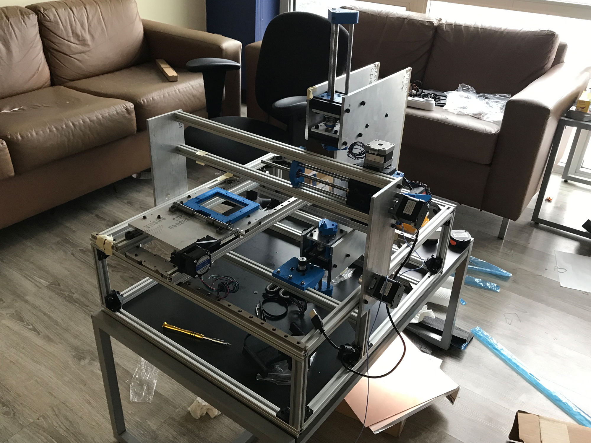
The Lobster in its new home.
Mechanical Next Steps
With two major systems installed, testing can begin once the software/firmware is ready. Additionally, we’ll have to cut down our PCB stock to the right size (3" x 4"), which we can do on campus.
For the build, our next priority is the x- and y-motion systems. The rails and carriages have already been assembled as part of the frame build, but we need to fine-tune alignment and install the required motors and sensors.
Software/Firmware Updates
Over the last week:
- The controls to tune the image masks were developed
- GUI to show the stages of the masking process for debugging was created
Computer Vision Controls
This week the controls that will be used to quickly debug the problems with the computer vision algorithm we developed. This was done by creating 6 sliders to control the threshold of pixel values that will be filtered out of the final image that is used for detection. The color type of the raw camera image is called HSV (Hue, Saturation, Value) this encodes the value of a pixel based on 3 numbers which represent the colour and light values of the given pixel. Each element of the HSV has two sliders to control the lower and higher limits of the pixels that will be removed in the masked image. So, 2 sliders for each of the Hue, Saturation, and Value parameters is why 6 sliders are required. This is duplicated for the wire and the hole for a total of 12 sliders. They each need separate sliders as the holes we are trying to detect are dark areas and the wire is a well-lit orange area. Each of these are masked separately and then combined into a final masked image. As an example, you can see in the picture below the first 4 sliders are for the Hue and Saturation of the holes. They are both set from 0 to the maximum value, allowing all pixels to move through the filter. The next two sliders correspond to the Value parameter which is set from 0 to 33, this allows only pixels with a “darkness” value lower than 33 to be added to the masked image. This isolates the holes from the rest of the background details as they are the only parts of the picture that are dark enough to get through this filter.
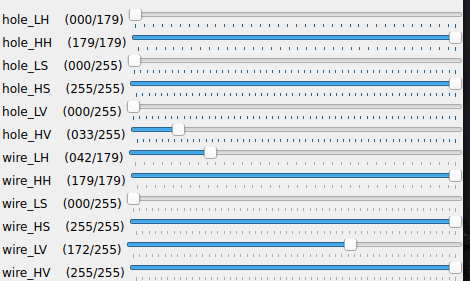
Controls to tune masking process.
Computer Vision Debugging
Also, a GUI was developed to display the images generated at each stage of the detection algorithm. This allows us to have a way to clearly see what the computer vision algorithm is doing at each stage when debugging. This was done so that when a problem occurs, we will be able to isolate the component that is not behaving how we expect and rapidly diagnose the problem.
Software Next Steps
Next week we will add wire detection and combine that with the hole detection process that was created earlier. Then the controls that were created this week will be used to tune the hole and wire detection. Then the remaining task will be to extract the position differences between the wire and the hole and determine the correct motor commands to align them.
