This week on The Lobster: The x- and y-axis movement systems are installed, the first milling/drilling head gets assembled, and we get a big steel box.
General Updates
A little over one week ago, we received the wrong size of bearing, limiting our ability to build all three milling/drilling heads. We initially found a local supplier who could get us the bearings and we were ready to order, but a miscommunication meant they were much more expensive than we thought. We’ve now sourced the bearings from another supplier, with a delivery date sometime next week, but in the meantime we do have some bearings for a partial build.
Mechanical Updates
Last week, we installed the wire feeder, via press, and PCB flipper to the machine. This week, the mechanical build continues:
- The x- and y-axis motion systems were installed
- The first milling/drilling head (out of three total) was assembled
Motion Sytems
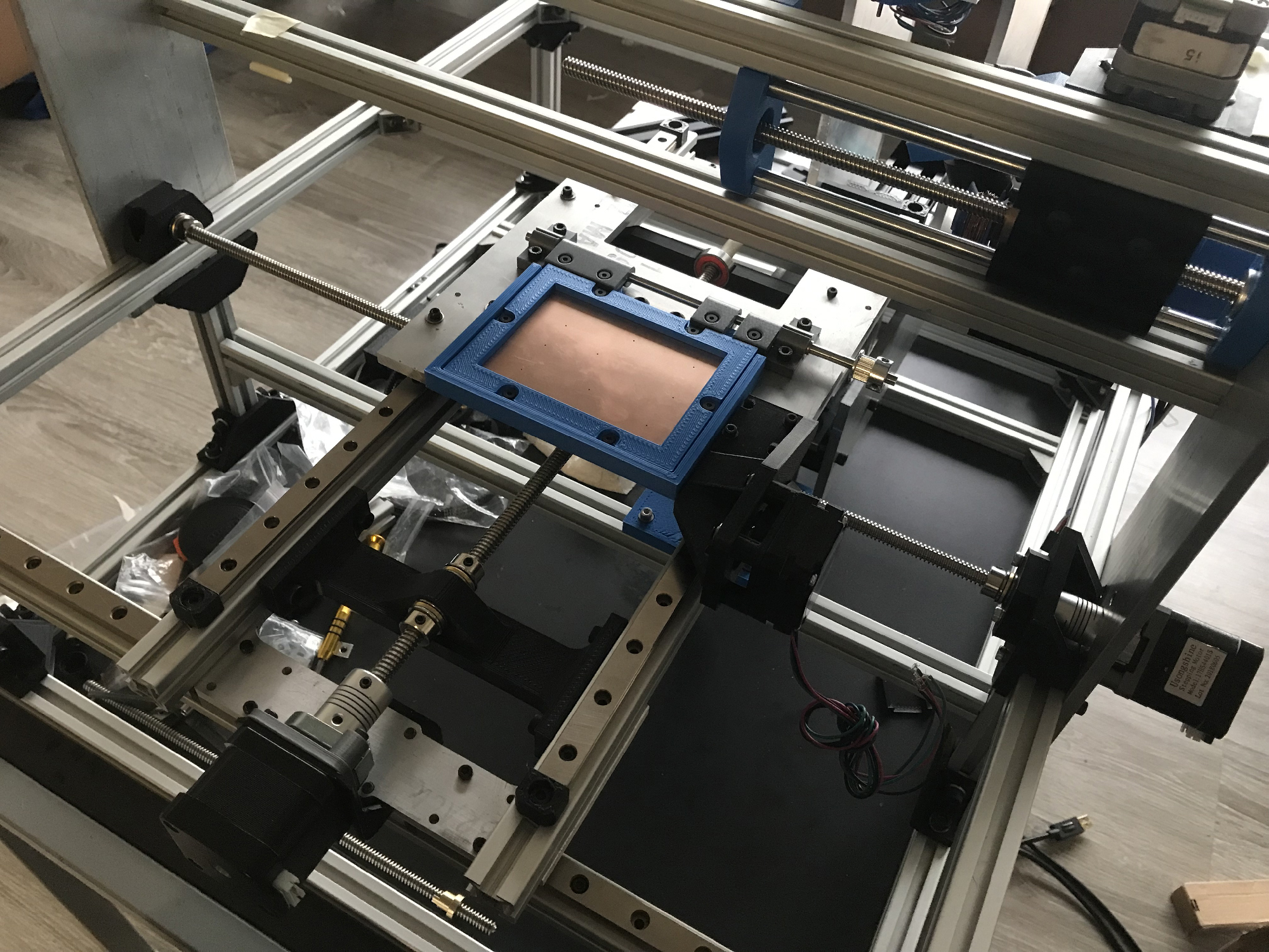
The motion systems are straightforward: each axis consists of a carriage moving on linear guides, actuated using leadscrews and stepper motors. The carriages and linear guides were previously installed as part of the frame build, and so the past week consisted of installing the leadscrews and stepper motors, and tuning their alignment.
Installing the stepper motors was simple, with the frame already having mounting holes for the x-axis motor, and the x-axis carriage having mounting provisions for the y-axis motor. The leadscrews are supported by deep-groove ball bearings to prevent radial displacement, and thrust bearings to prevent axial displacement.
To ensure the leadscrews are parallel to the linear guides, the machine was designed so that the location of these bearings could be adjusted. As a side-effect, this meant aligning the the bearings and leadscrew was a time-consuming process, but now the motion system is aligned, runs smooth, and has no noticeable backlash or play when disturbed by hand.

A close-up look at the x- and y- leadscrews installed and connected to the carriages.
Milling Heads
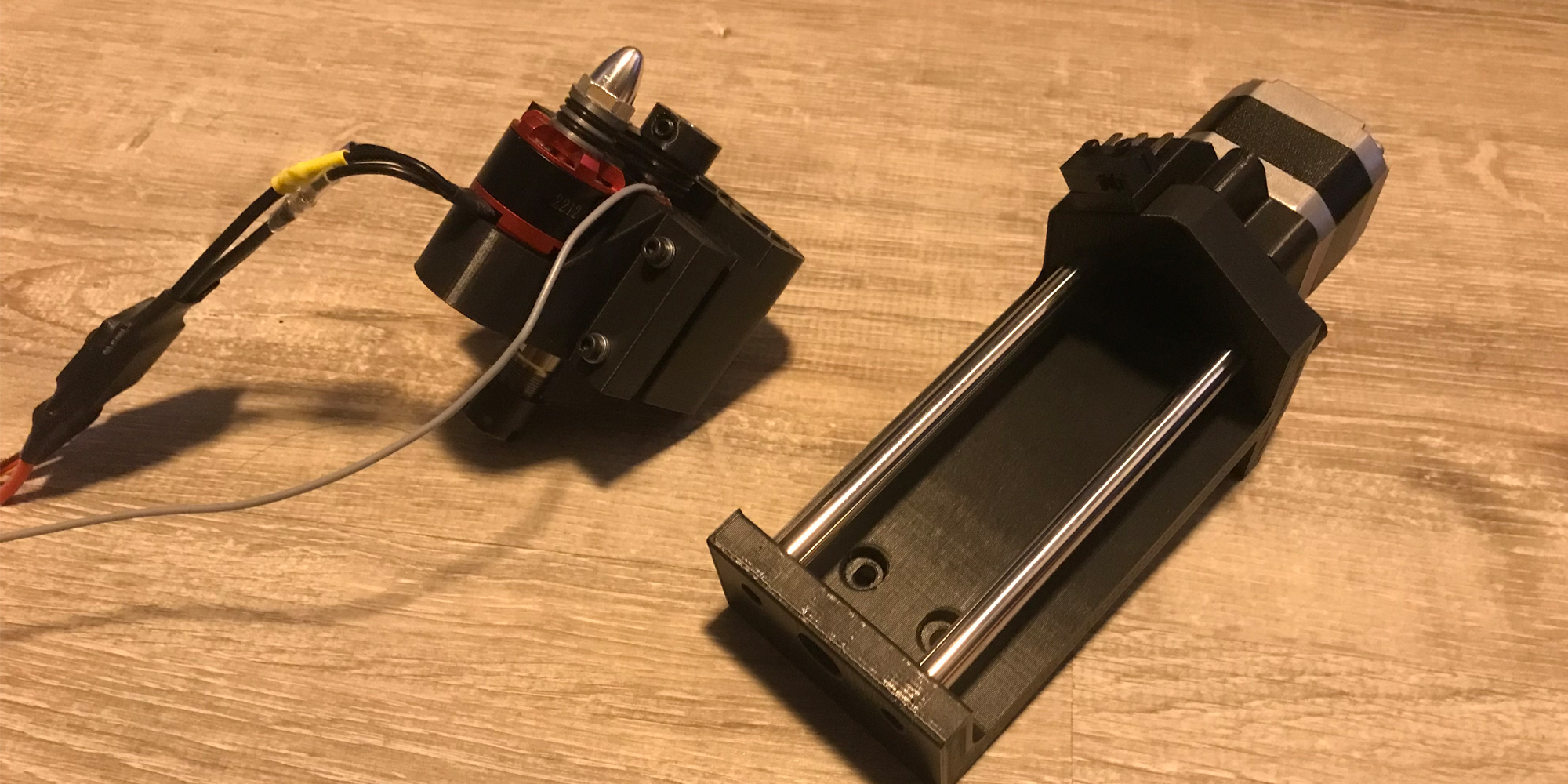
The milling and drilling heads are also straightforward; a spindle is pulley-driven by a brushless DC motor, and the head is moved in the z-direction by a leadscrew and stepper motor. Much like the wire feeder, the main body was designed for and manufactured using 3D printing, with the parts being assembled using screws or press-fits.
Additionally, to support conductive probing (in which we determine the relative z-position of the milling/drilling bit by touching the tool to the PCB), we need to conduct a signal to the milling/drilling bit. The easiest way to accomplish this is to conduct through the bearings; while not ideal due to lubricants in the bearing, our testing has shown that the overall resistance of the bearing is low enough for us to work with. To connect the bearing (and subsequently, the spindle) to our control electronics, copper tape and wire are used to connect to the bearing.

The milling head assembly, ready to be wired and installed.
Unfortunately, due to the bearing sourcing issues we’re facing, we were only able to assemble one milling/drilling head (each spindle requires two bearings, and had a single pair already on hand). On the bright side, while waiting for the bearings, we can get a head start on the 3D printed components (approximately 7 hours of printing per assembly!).
On the topic of Bearings
Our bearing situation is an interesting one, primarily because we would like to use a specific type of bearing. Due to the axial loads we expect to encounter in milling and especially in drilling, we would like to use angular contact bearings to support both radial and axial loads. Unfortunately, at the small size we’ve specced (to reduce the overall size of our assemblies and machine), these bearings are hard to source domestically at a reasonable price.
In general, we believe that using bearings specifically designed for axial loads is a best practice in this scenario, however we also acknowledge that we’re building a prototype that drills very small holes. Thus, while we have our fingers crossed that the incoming bearings will work out, we also have backup plans that user regular ball bearings (rated for much smaller axial loads).
Mechanical Next Steps
The mechanical system is now almost fully ready for testing; all that’s left is installing limit switches for all moving components, which will be done this weekend. Our immediate priority is then to test each individual system, make changes and modifications as necessary, and then work towards full integration.
Once the bearings arrive, we’ll assemble the remaining two milling/drilling heads, and in the meantime we’ll also take a look at auxiliary systems (dust management, full enclosure) that have been previously sitting on the backburner.
Software/Firmware Updates
Over the last week:
- Computer vision was tested on the machine
- Problem with hole detection was encountered and fixed
- Wire detection was developed
Computer Vision on the Machine
The computer vision was tested on the Machine this week. However, it is not completely integrated into the Raspberry Pi just yet, so for now it will be run off a computer. Nonetheless, the camera and PCB was mounted and positioned exactly how it will run when everything is integrated. For the most part this test was successful as the holes could still be detected except for a small problem I’ll explain in the next section.
Hole Detection Problem and Solution
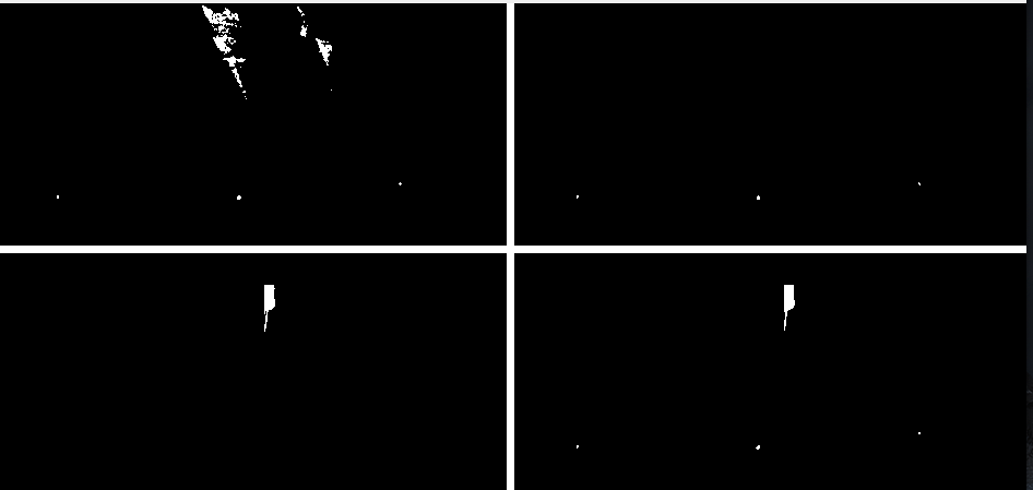
Testing the hole detection went better than expected as there was a large change in lighting conditions from the old testing room to the lighting inside the machine. Changes in lighting conditions are difficult for computer vision algorithms and normally would require tuning and calibration. The problem is that the wire cutters are black, which is the same colour as the holes we are trying to detect. In the top left quadrant of the image below you can see the noise this created. This noise is a problem because the software is unable to distinguish the noise of the wire cutter at the top of the image from the 3 holes along the bottom of the image. This problem was solved using a region of interest which is like “cropping” the image. Since the camera and wire cutters are mounted to the wire feeding head, the wire cutters will always be in the same position relative to the camera and hence the same position in the image. So, we can use the same region of interest at any time regardless of the position of the machine and crop out the cutters. In the top right quadrant of the image below the result of this process can be seen where all the noise is eliminated and the three holes are left over.

Hole and wire masking and combination.
Wire Detection
Wire detection was developed and tested on the machine. Unlike the hole detection, the wire detection worked perfectly after some initial tuning using the controls created last week. In the bottom left quadrant of the image above you can see the wire feeding nozzle and the wire that is extruded from the nozzle. Finally, this image was then combined with the hole image created above to create an image containing just the holes and the wire as seen in the bottom right quadrant on the image above.
Software Next Steps
Next week the combined mask image will be used to draw a circle on the holes and a line on the wire in the original video. Then the points of the holes and the point at the tip of the wire can be calculated. Once the points are found these can be used to determine the pixel offset between the wire and the hole. This offset will be converted to a physical distance of millimeters and output so that the motors can use this information and move the machine and align the wire to the hole.
