What’s new for Week 5? The first milling head is mounted to the machine, we start to clean up our wire routing, and we take a look at dust collection.
General Updates
First and foremost, the bearing saga continues: we’re still waiting on the additional bearings, but this hasn’t significantly impacted our schedule. Functionally, the remaining two milling heads are identical to the first, and so having one assembled and mounted is sufficient for testing.
Next week is another update meeting with our supervisors (Feb 13, specifically). We plan on showing some videos of our machine’s individual functionalities (movement, conductive probing, computer vision), and we’ll also discuss our remaining steps before final demonstration and symposium.
Mechanical Updates
As of last week, the only remaining actions (in terms of what we could do without the bearings) were to mount the first milling head and install limit switches, and this week, we did just that.
We also began progress on the auxiliary systems: dust managment and a full enclosre. We had previously defined these as “nice to haves,” as they are not critical to the main functionality of the machine (which is to autonomously produce 2-layer PCBs), and so there’s still some design work to be done before we build these systems.
Milling Head and Limit Switch Install
The milling head and limit switch install processes were straightforward, with the components being screwed to the frame. As with many other parts of the machine, the miling head and limit switch were designed to have flexibility in their mounting locations, and so we spent some extra time to ensure that all the components were mounted properly. This was especially important with the limit switches, as we had to ensure we had full range of motion without collisions.
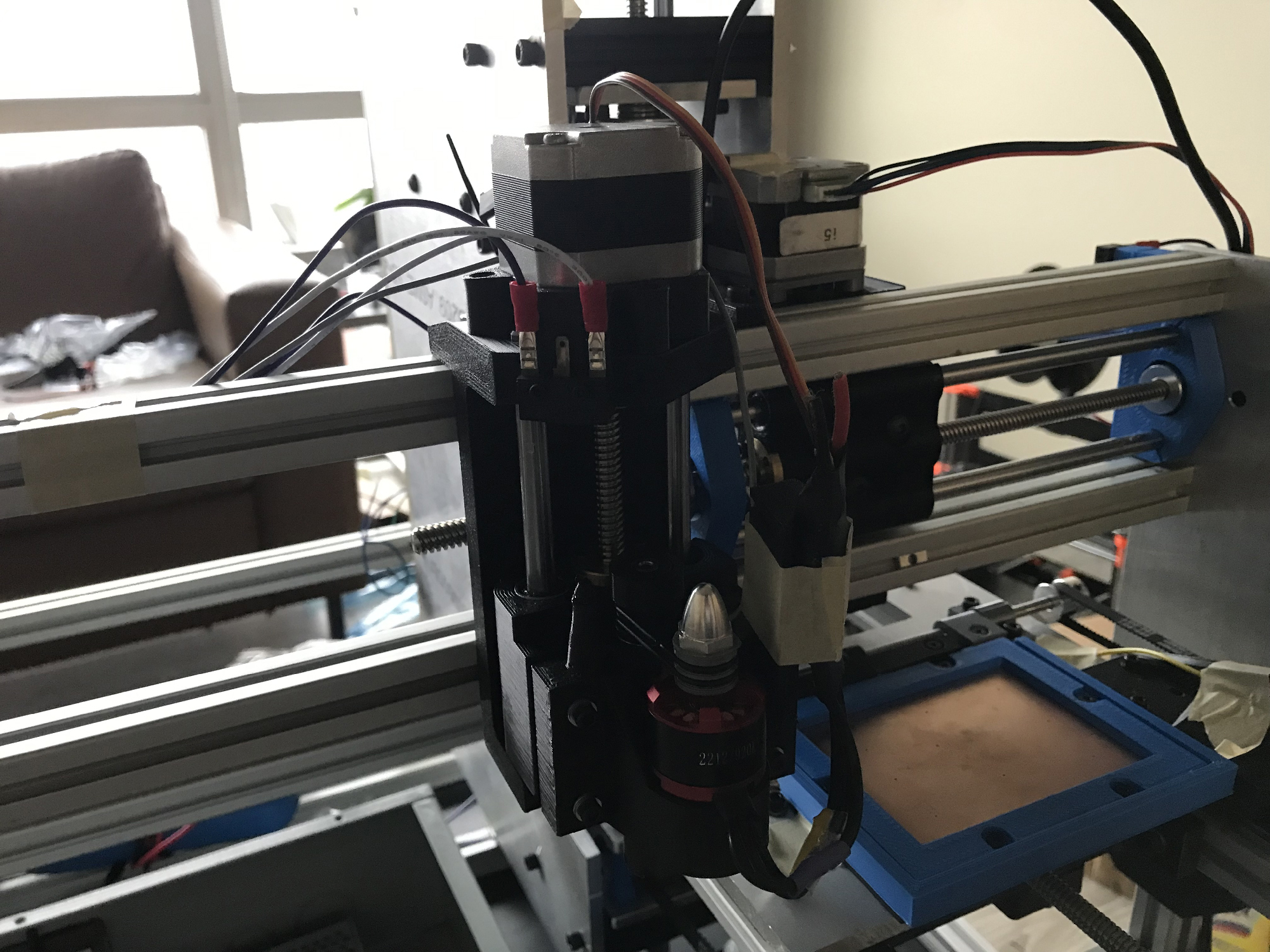
The first milling head assembly, installed to the machine.
Dust Management
In milling and drilling our PCBs, we will inevitably produce dust. We need to manage this dust for health and safety reasons, but we would also like to manage the dust so that it doesn’t interfere with our various processes. For example, dust around a via hole may inhibit a proper via connection, and dust on the PCB may be thrown around when the PCB is flipped.
Our targeted solution is dust collection, in which we use some form of suction to pull dust away from the PCB. If properly implemented, this would be the most autonomous solution for managing dust, requiring no human input. A straightforward implementation is to use a commercial vacuum, which would certainly provide ample suction for the small amounts of dust we’re producing. In fact, a commercial vacuum is what we use when testing our machine.
However, we are removing small amounts of material and therefore producing small amounts of dust, and so we believe a regular vacuum may be overkill. Instead, we’re first investigating using a custom dust collection setup, with a blower fan and a small cyclone separator, essentially a scaled-down version of a carpenter’s dust collector.
We first tested a blower fan we had on hand, but it didn’t produce much suction at its rated voltage (which makes sense, because it’s a cooling fan designed for air flow rather than pressure). Our next attempt will use a custom designed and 3D-printed blower fan, the design of which we’ll base off of larger scale blower fans for wood dust collection.
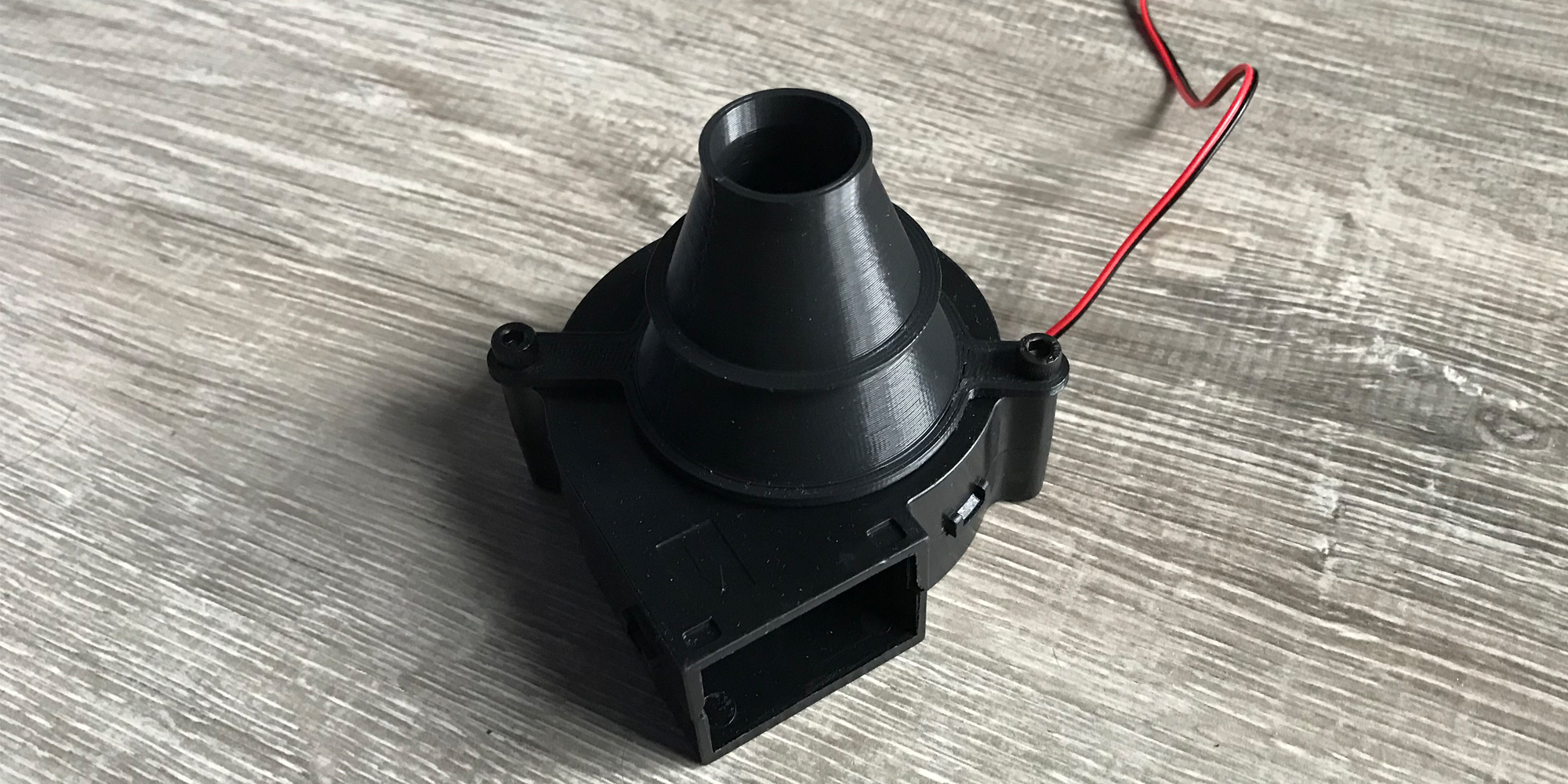
The first blower fan we tried, with a shroud to help increase suction.
Mechanical Next Steps
Our immediate priority is still to finish the remaining milling heads (dependent on the bearings arriving), with our work in the meantime focusing on dust management and the enclosure.
As always, if a mechanical concern arises in our testing, that will become our top priority.
Software/Firmware Updates
Over the last week:
- Hole and wire overlays were created
- Physical adjustment function was developed
Hole and Wire Overlays
To create the overlays contour detection is run on the masked image created last week. This results in an array of contours. Each item in this array can be bounded either by a box or a circle. For the wire a bounding box is used and the holes use a bounding circle. These bounding shapes have a known center point and dimensions which can be used to calculate the points of interest like the tip of the wire and the center of the holes. These points are also used to draw the overlays over the hole and wire as seen in the image below. One problem that I encountered was that if multiple holes were in the frame they were all detected. This is a problem because the machine can only fill one via hole at a time and it needs to fill the one that the G-code assumes it is filling. This problem was solved by calculating the distance between each hole and the tip of the wire and then only focusing on the one that was closest to the wire. This is a suitable solution as we are confident that with the motor encoders we will be able to position the hole with enough accuracy so that the right hole will always be the closest to the wire.
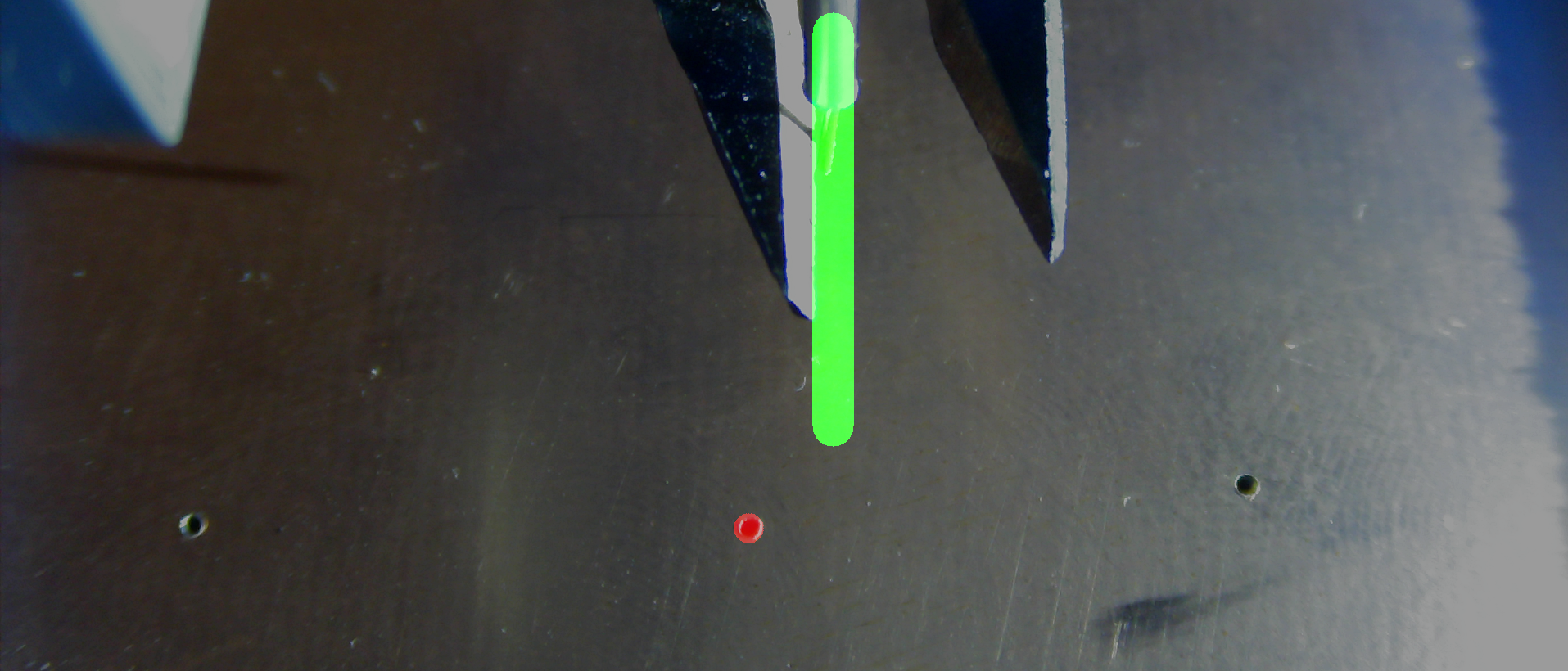
Hole and wire overlay.
Physical Adjustment Output
The goal of the computer vision software is to output physical adjustments that the motors can use to position the hole under the wire. First the distance in pixels in the horizontal and vertical directions was calculated using the points of interest found above in the bounding and overlay part of the code. Then a factor to convert the pixel distance to millimeters was found by physically measuring the area that the camera can capture (at the distance that the PCB will be) and dividing by the screen size in pixels. This was done 5 times for each axis and the results were averaged resulting in a pixel/mm factor of 0.0232222. These values are then output by the program to be used by the firmware.

Computer vision output.
Software Next Steps
The next step for the software is to move the program from the external computer to the Raspberry Pi inside the machine. Then, perform more testing and tuning to ensure that the behavior of the program is unchanged after being integrated into the machine. Finally, full system tests will be run to ensure this computer vision software is robust and functions as expected while all other subsystems are running.
Electrical Updates
This week we took a look at our wire routing, to make sure we were running wires efficiently and safely. Right now, most of our wires are simply taped down as a temporary measure; once we’re satisfied with all of the routing, we’ll add proper sheathing, tie downs, and cable chains to tidy everything up.
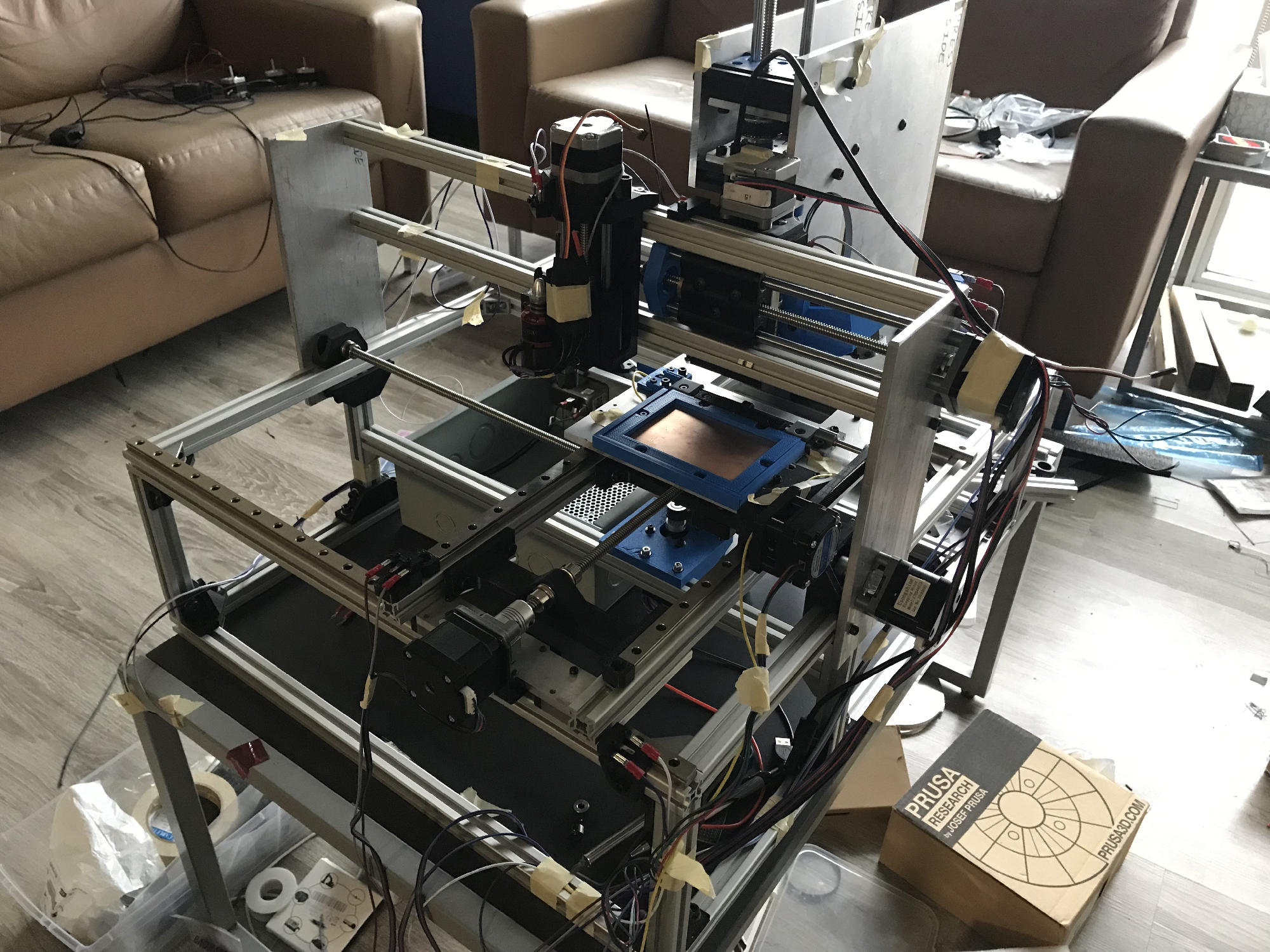
The machine shortly after wire routing work was started, with wires temporarily taped down.
