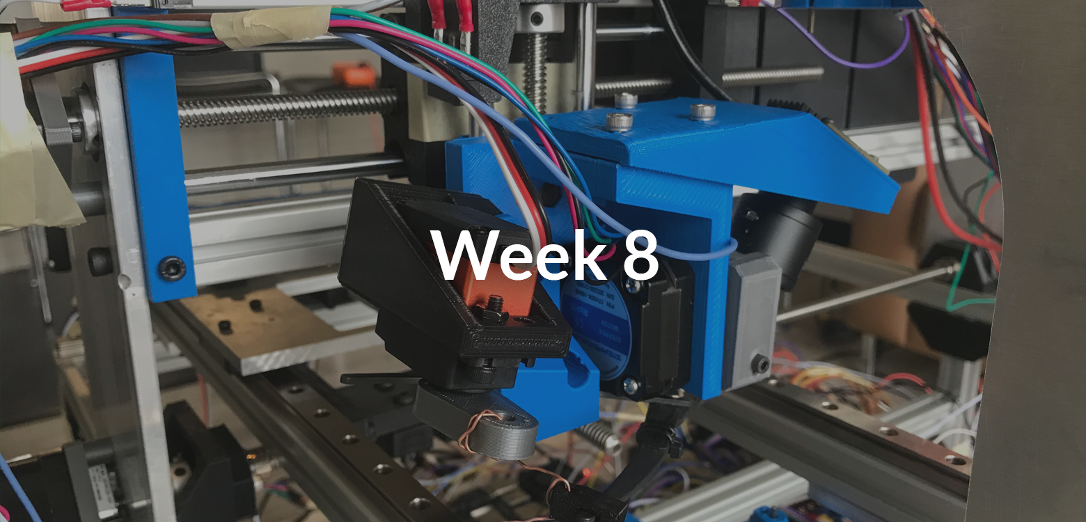
We continue to move towards demonstrating our machine (and have a few more hiccups along the way).
General Updates
Over the past week, we’ve consulted MME staff regarding safety, and are on the right track to having a safe machine for symposium. We’ve also confirmed that our demonstration with our supervisors is next week, on March 9th.
While testing, we also hit a slight road block - a component on our control board failed, leaving us with limited functionality. Fortunately, fast shipping from Digikey and some careful soldering let us repair the board, although we did lose a bit of testing time for some features.
Mechanical Updates
During testing, we identified some issues with motion systems and the wire cutter, which we addressed over the past week.
Unobstructing Motion
In a previous update, we discussed the PCB flipping system that is part of the PCB carriage. This system is actuated and therefore requires wires running to it, and we experienced some interference with these wires and other components. While the wires had enough length to allow for full movement, they would occasionally catch on other components, which could be damaging.
To address this issue, we decided to implement cable drag chains to protect the wire and constrain their movement. To save money, we chose to 3D print the cable chains, and to ensure a perfect fit, we designed them for our specific application.
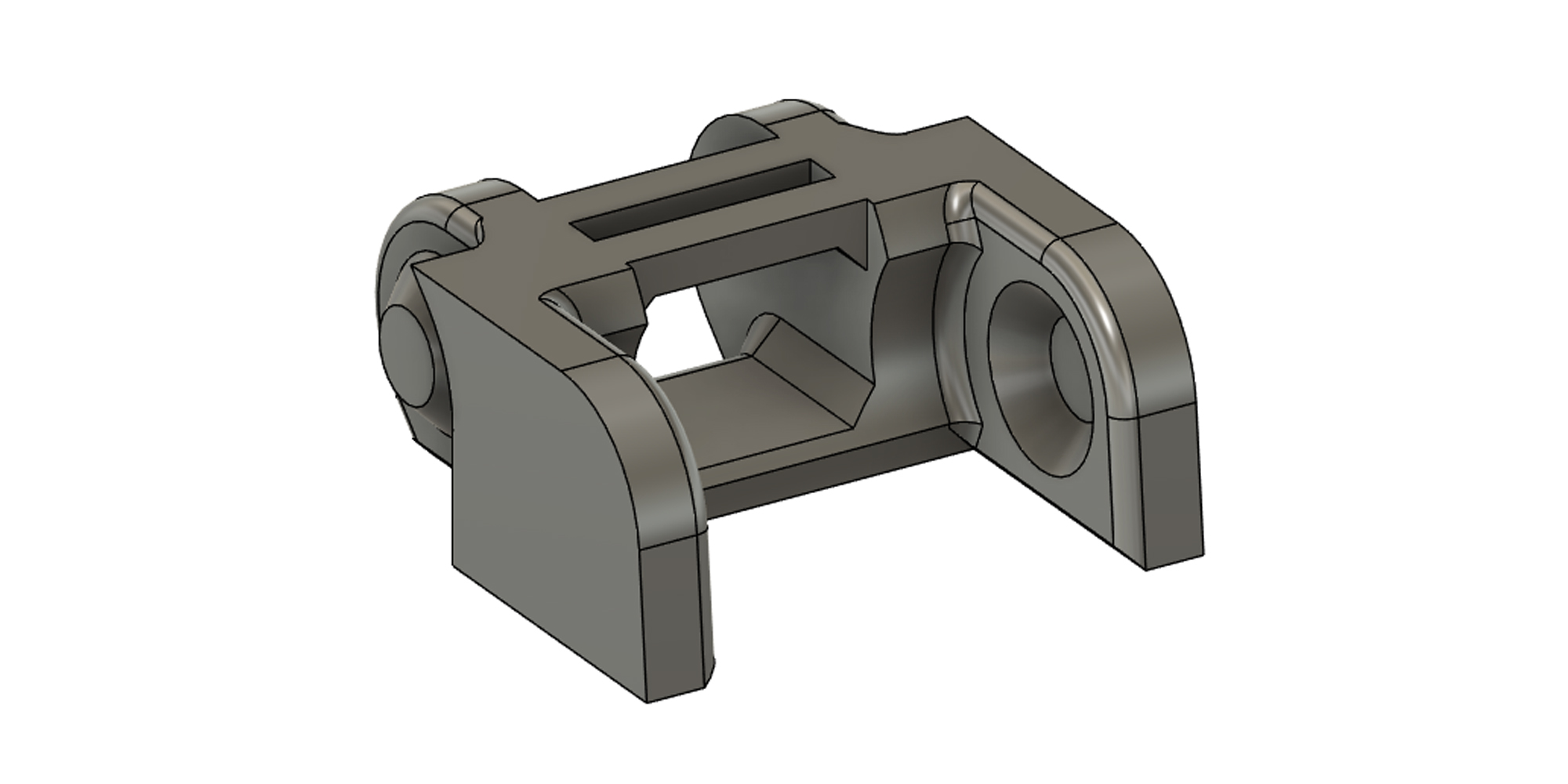
A 3D CAD render of a custom cable drag chain link.
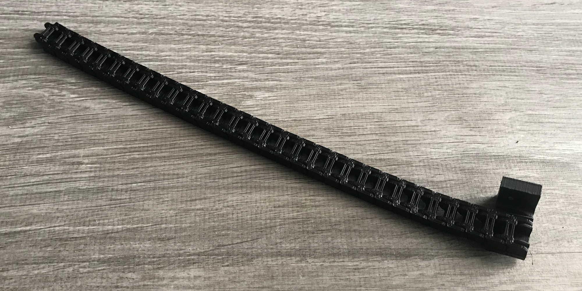
The full cable drag chain, ready to be installed.
Cutter Replacement Parts
In our Week 6 update, we discussed replacing the wire snippers used in the cutter, due to a damaged and dull blade. The new wire snippers work well and have remained sharp, but they have a slightly different geometry compared to the older cutters. While the wire cutter system still worked with the new cutter, there was some interference between parts that would eventually cause failure.
As a preventative measure, we designed a new servo motor holder to better position the servo, and implemented a new wire snipper connector to match.
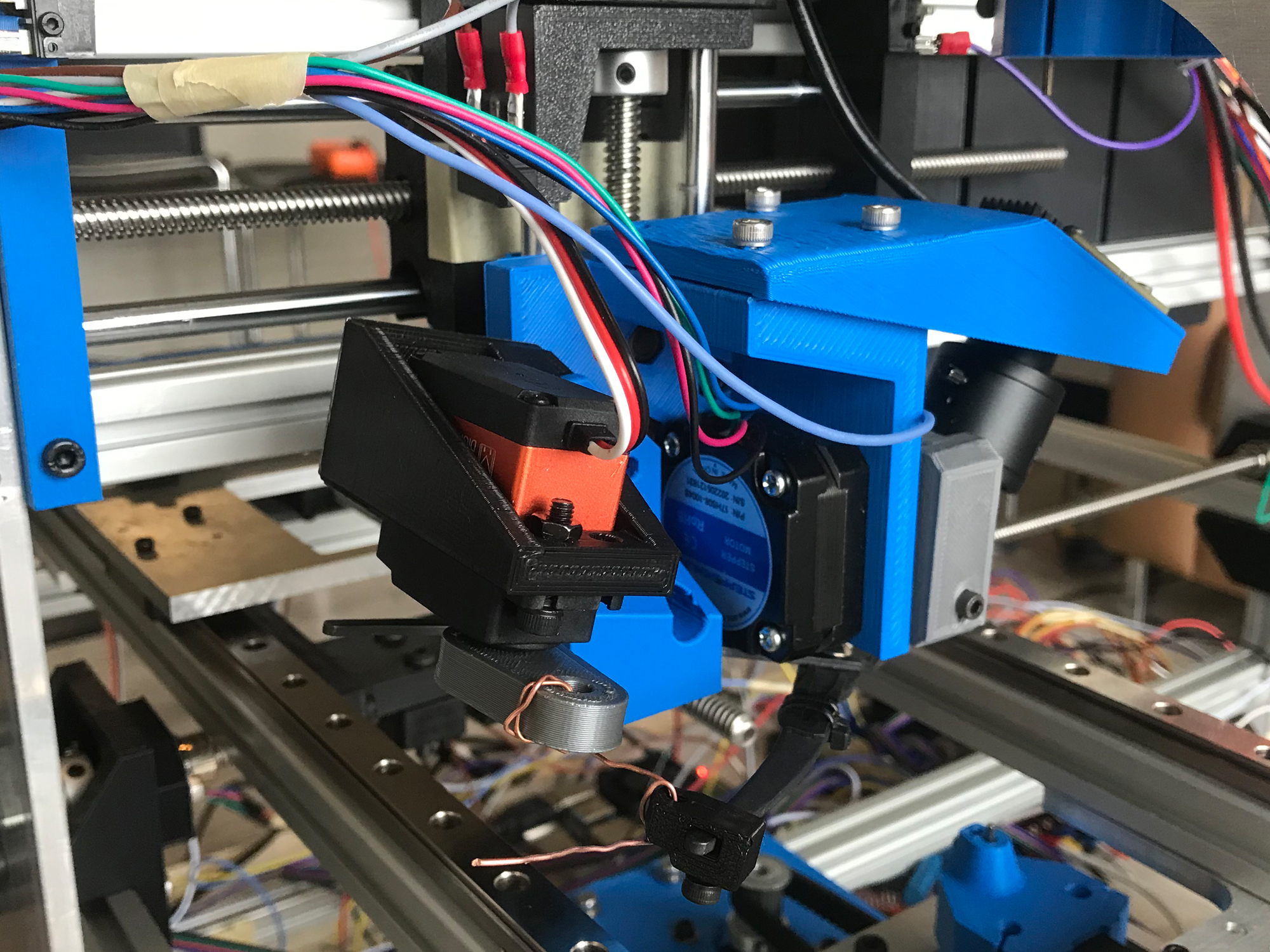
The wire cutter system, with new parts in black (versus old parts in blue).
Software/Firmware Updates
Over the last week:
- The computer vision program was tested
- Advanced wire detection was created
Testing
The computer vision program was tested on the machine. Everything functioned as before but there was a problem with the wire detection. The previous wire detection algorithm assumed that the wire would be relatively straight and contact the PCB under the wire feeding nozzle. This assumption was made to simplify the problem and scope of the algorithm because it would reduce the tuning required and increase the robustness of the program against external factors like lighting and noise in the image. Testing was performed with all the LEDs and heads in the position they will be in when run in the full machine process. The results of the testing was that only minimal tuning was required to have full functionality in bright and dark lighting conditions. This showed us that the software was very robust. Due to this a more advance wire detection algorithm could be used so that the straight wire assumption would not be necessary. Also, when testing wire cutting, we found that due to how the cutters are positioned and how they cut the wire, the wire will always be bent slightly to the left. For these reasons an advanced wire detection algorithm was made.
Advanced Wire Detection
The advanced wire detection works in a similar way to the hole detection algorithm. First the region around the wire feeding nozzle and between the clippers was cropped. Then the standard blurring and masking was run to detect orange features in the cropped image, tuned with the controls from earlier. Normally this would pick up the PCB too as it is the same copper color as the wire, but the LED’s shining directly on the PCB wash it out enough from the camera’s perspective that the PCB looks whiter than orange. This allows us to almost completely isolate the wire as seen in the left half of the image below. However, you can see there are still some patches of noise around the wire. To remove these a contour detection algorithm was used. Once the contours of all the patches are found the wire is identified as the contour that starts from the top middle of the frame because even when the wire is bent it still comes out of the nozzle at this point. After the wire contour is identified it is saved and used to draw a bounding box around the wire. The wire contour and bounding box can be seen in the right half of the image below.

Wire detection masking on the left. Final detected wire with bounding box on the right.
The bounding box is used in debugging as a visual indication to ensure the software is detecting the wire correctly. For the actual functionality of the program what is important is the position of the tip of the wire. The wire contour is a list of pairs of points which define all the lines in the contour. To find the tip of the wire the program goes through this list of points and finds the one that has the lowest y coordinate. This is the lowest point on the wire; hence it is the point on the tip of the wire. The red dot in the image below shows where the tip of the wire is. Detecting the wire tip in this way makes it very robust as no matter how the wire is bent by the cutters the software will always be able to find the tip of the wire. With this new wire detection algorithm, the point at the tip of the wire can be used with the hole detection and adjustment process that was made previously. All these processes combined create the complete robust computer vision system that is ready to be integrated into the machine and control flow.
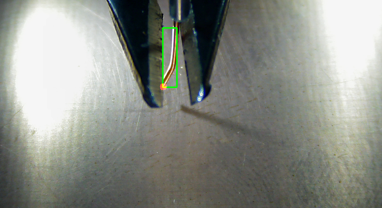
Detected wire tip in red and bounding box in green.
Software Next Steps
Next the program needs to be modified so that it can be seamlessly integrated into the firmware and control flow. To do this an API will be created for this software. Currently the computer vision software works by performing all the steps and repeating them in a loop forever until the user manually stops the program. In the control flow the software will need to run once and return the adjustments needed to fit the wire into the hole then perform control tasks like moving the motors. Adjusting the existing software for integration involves creating functions that the control flow can call when needed to get a single adjustment. After this full system integration testing can occur.
